Brand Name:icchipcn.com
Condition:New
Type:Logic ICs
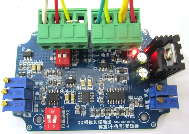
Using original imported chips, stable performance. The excitation is adjustable, and the applicable sensitivity is 1-3mV/V.
1 Overview
This module can convert DC small signal voltage (0-50mV) into 0-5V/10V voltage output and 4-20mA current output.
Applied to full-bridge strain sensors (weighing, force measuring, tension, pressure sensors), DC differential small-signal voltage conversion.
Fully waterproof shell, screws and lead holes are made of 704 silicone rubber, which can be soaked in water without any problem.
Advantages:
1: Applied to a full-bridge strain sensor, it can output an accurate 10.000V, which is convenient for range calculation. Compared with other modules, some are less than 10.000V.
2: There is a sensor disconnection alarm output function, and the upper limit or lower limit alarm can be selected.
3: Applicable to almost all full-bridge strain sensors, see below for specific principles.
In a nutshell: the input voltage signal is greater than 16.7mV, which can be amplified by 600 times to 10V. Signals from 8.3mV to 16.7mV can be amplified by a factor of 600 to 5V. If it is less than 8.3mV, it is enough to change the value of the component and increase the magnification. You need to study it yourself.
The 20mA output part can convert the input voltage signal greater than 16mV into 20mA. If you select "x2" for "Current scale", the input voltage signal greater than 8mV can be converted into 20mA.
Therefore, this module has a wide input range and is suitable for almost all full-bridge strain sensors.
Input voltage signal = input sensitivity x sensor excitation voltage. For example: a 1.5mV/V sensor is connected to a 10V excitation voltage, and the full-scale output is 15mV.
Compared with other modules, the input sensitivity has a variety of options, and the sensor excitation voltage is also available in a variety of options. Combining them together makes the classification very complicated. To put it bluntly, the adjustment range is too small and the design is not comprehensive.
Parameter:
Power supply | 24V(15V-26V) |
Input sensitivity | 1-3mV/V |
Sensor excitation voltage | 5.2-10.2V adjustable |
Excitation voltage load capacity | 85ohm/110mA output |
Signal input impedance | 20 kΩ |
Voltage output | 0-5V or 0-10V,Output resistance
1kΩ |
Current output | 4-20mA, load resistance 0-500 ohm |
Conversion output precision | 0.05% F.S |
Working temperature | -20 to 80℃ |
Weight | 100g |
Signalterminal: 5.08 pluggable terminal
Power + -: The standard power supply is 24V (15V-26V), because the internal voltage is regulated to 12V, and theoretically it is a few volts larger than 12V.
IO: 4-20mA output VO: voltage output
+EXC –EXC: Excitation voltage output for sensor
+SIG –SIG: Signal input, that is, the sensor output is connected here
2: Design principle:
The whole circuit consists of 4 parts
1: Power regulation and conversion, 12V regulation, 9V regulation, -9V conversion.
2: Pre-stage differential amplification, using OP07C to achieve differential amplification and zero adjustment, fixed amplification of 50 (49.9) times.
3: Voltage output part, 5V/10V voltage output, and the adjustable voltage amplification output is realized by TL064C.
4: Current output, the adjustable current output is realized by TL064C.
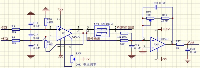
SW1 is a DIP switch, responsible for "voltage gear" (marked K1 on the PCB) and "current gear" (marked K2 on the PCB).
The differential voltage of the front stage is fixedly amplified by 50 times. Assuming that a 2mV/V pressure sensor is used, the excitation voltage is 10V, the full-scale output of the bridge is 20mV, and it is 1V after the amplification is 50 times.
The voltage output part is an adjustable gain. When the "voltage gear" is in the "OFF" (5V) position, the voltage gain is (40.2+(0-20 adjustable))/10=4-6 (times).
That is to say, it can output 5V at a full scale of 20mV.
When the "voltage gear" is in the "ON" (10V) position, the voltage gain is (40.2+(0-20 adjustable))/(10 in parallel with 10)=8-12 (times).
That is to say, it can output 10V at a full scale of 20mV.
Therefore, the SIG signal is actually amplified by 200-300 times and 400-600 times. Inversely, if the output is 10V, the minimum value of SIG is 10V/600 times = 16.7mV.
Therefore, if it is a 1mV/V bridge and the excitation voltage is 10V, the output will not reach 10V, but can reach 5V. If you have to output 10V, the solution is to increase the R15 resistor to 91K. The input voltage can be positive and negative, and the amplified output is also positive and negative. The maximum output positive voltage is 12V, and the maximum negative voltage is -9V.
Current output part:
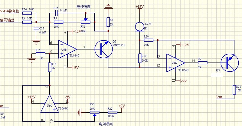
If the signal input is too small and the output can not be adjusted to 20mA, turn the "current gear" (marked K2 on the PCB) to the "ON" position, and the current output will be doubled.
The advantage of this design is that any sensor with an input sensitivity of 1-3mV/V can be used and can output 20mA.
DIP switch:
SW1 is marked with K1, K2 on the PCB, and 10V (X2) is "ON", which means the gain is doubled. 5V (X1) is "OFF" is normal gain.
All signals are common negative (GND). Also, the internal resistance of the voltage output is 1 kΩ, so the internal resistance of the voltage acquisition module must be large. Using our module with 10V specification, the input resistance is 150K, and the voltage loss is 1/151. Of course, you can fine-tune the output gain to compensate.
In summary:
This module is a general small-signal amplifying and converting module, which can achieve many functions by changing the component parameters. An isolated power supply or a signal isolation chip (AMC1200) can be used to achieve high and low voltage signal isolation conversion.
Power section:
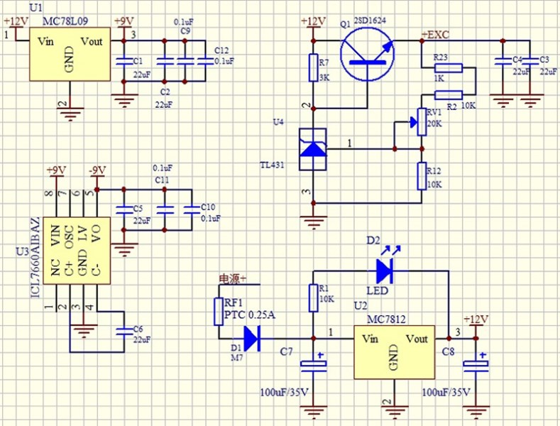
The schematic diagram and the PCB are completely consistent. If you don’t understand it, don’t ask, and study it yourself. The module has been tested before leaving the factory to ensure that the function is intact. It must be connected to the sensor for calibration before it can be used normally.
Calibration adjustment steps
1: Adjust the excitation voltage,
Connect the sensor, measure +EXC and -EXC, and adjust the excitation potentiometer to make the voltage meet the requirements. Do not move after the excitation voltage is adjusted.
2: Zero adjustment
A: Voltage adjustment
First, put the sensor in the no-load state, adjust the voltage zero potentiometer, and measure the VO output terminal at the same time, so that the value is close to zero. The ideal is zero but it is difficult.
B: In the same way, adjust the current zero-point potentiometer and measure the IO output terminal at the same time, so that the value is 4mA.
3: full scale adjustment
A: Load the sensor with a certain weight, it is recommended that more than 80% of the full scale, preferably 100%, calculate the theoretical output voltage value according to the ratio of the loaded weight to the full scale, and adjust the voltage full scale to make the VO output value equal to the calculated theoretical value output voltage value.
B: In the same way, adjust the current full scale to make the IO output value equal to the calculated theoretical output current value.
4: Repeat steps 2 and 3 to verify whether the value is accurate.
Here I will say that you can use a standard signal source to simulate the sensor to verify the performance of the module. –SIG should be connected to –EXC.
If it is not loaded with 100% weight, the theoretical output value is not 5V, 10V, 20mA.
In some applications, it is necessary to judge the pressure by outputting the analog value to determine the action of the actuator. If the sensor is disconnected, the unrestricted action of the actuator may lead to serious consequences. Therefore, when the sensor is disconnected, we need it to output the minimum or maximum value. The purpose is to let the host judge that a failure has occurred. Based on this purpose, a bias circuit is added to the input stage in the design, and the SW2 DIP switch is used to control whether it is used or not. The circuit structure is as follows:

Dial to "ON" is to add bias, the sensor disconnection output maximum value. The maximum voltage is 12V and the maximum current is about 30mA.
When it is turned to "OFF", no bias is added, and the sensor is disconnected and outputs the minimum value.
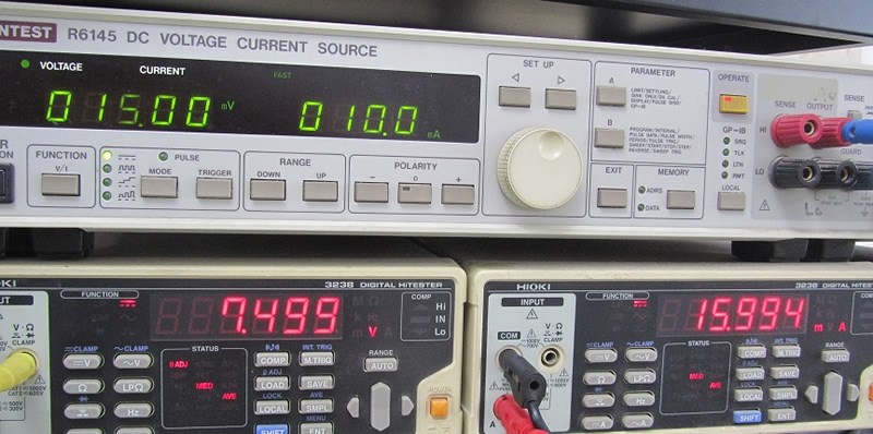
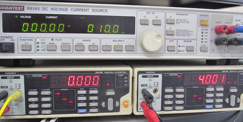
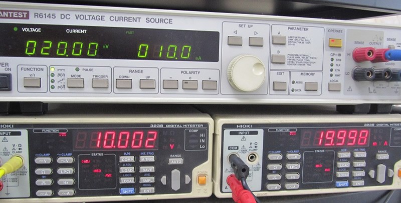
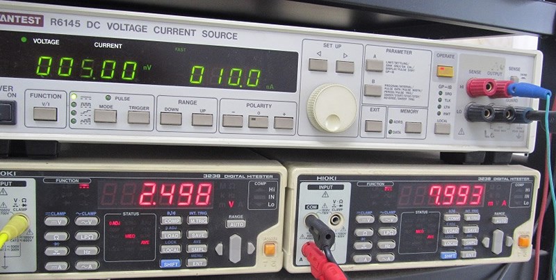
The following is a simulation of the sensor using a standard signal source to verify the performance of the module.
Input=0mV, measured VO=0.000V IO=4.001mA
Input=20mV, measured VO=10.002V IO=19.998mA (theoretical value 10.000V 20.000mA)
Input=0mV, measured VO=2.498V IO=7.998mA (theoretical value 2.500V 8.000mA)
Input=10mV, measured VO=5.001V IO=11.998mA (theoretical value 5.000V 12.000mA)
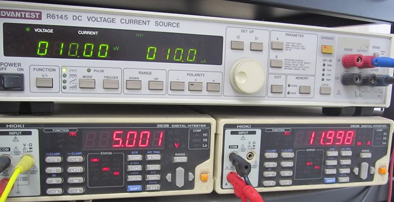
Input=15mV, measured VO=7.499V IO=15.994mA (theoretical value 7.500V 16.000mA)
