Type:Logic ICs
Condition:New
Supply Voltage:V
Dissipation Power:W
Operating Temperature:C
Application:0
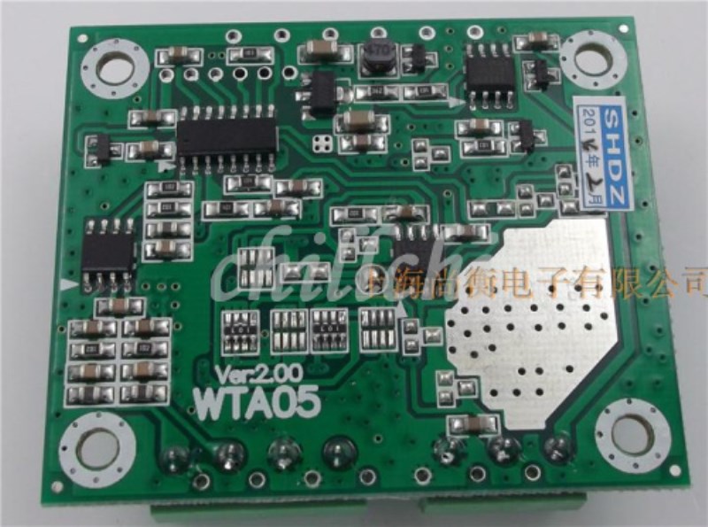
No.:WTA05
Color classification:4 ~ 20mA ~ 5V 0 ~ 10V 0 ~ 20mA 0 ~
Decoration and construction content:Purchasing materials
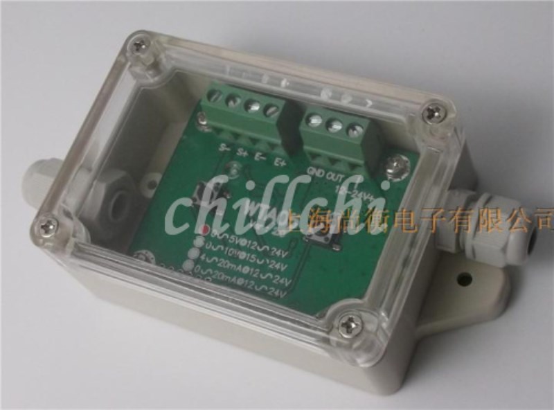
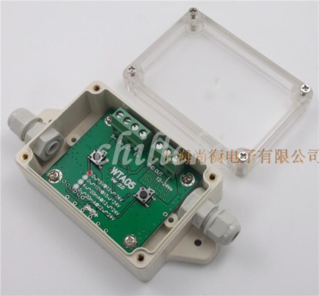
WTA05 intelligent weight transmitter
Is an advanced version of WTA03, supports 8 to 350 1 ohm load weighing sensor, the ability to resist interference.
Added 0 ~ 20mA output model (need to book, please contact the seller before the shoot, thank you for your support!).
Ordinary models have all the cash supply.
Input / output characteristics:
Input load: 350Bridge type sensor with ohmic resistance:1~8A;
ADSampling rate:40SPS
Input voltage: 12~24V(4~20mA,0~20mA,0~5V),15~24V(0~10V);
Output load: Voltage output: More than10KOmega;
Current output: (=Power supply voltage- 6*)50Unit: Ohm (ohm);
Output linearity: Be better than0.05%(0.5%);
Output ripple: Less than or equal to5mVp-p;
| Be careful:WTA05Only one of the signal output, and can not support a variety of output at the same time |
Output range: 4~20mA: at least3~21mA;
0~5V: at least-0.1~5.1V;
0~10V: at least-0.2~10.2V;
Temperature drift of the whole machine: Less than or equal to80PPM/(c0~40C);
Less than or equal to150PPM/(c-20~60C);
Power consumption of whole machine: Less than or equal to12mA1individual350Ohm sensor,24VPower supply voltage;
Comprehensive accuracy: Be better than0.2%(30CTemperature difference.
Set filter factor:
In order to meet the application needs of different occasions,WTA05Transmitter set the filter coefficient setting function, the user can combine their actual application of speed and accuracy requirements, reasonable choice of filter coefficient, in order to achieve the speed and accuracy of the best balance.
In the power down state, while holding down"K1"And"K2"Do not put, and then pass the power to the transmitter, waiting forLEDContinue to light up, loosen2A button, at this time,LEDBegan to enter "flashing lights several times, and then put out about1More seconds, and then flashing......"In the cycle, the number of successive flashes in a blink cycle is the filtering factor.1~12, the smaller the coefficient, the faster the output response, but the greater the noise, the greater the coefficient, the slower the output response, but the smaller the noise.
At this time by once"K1"The flicker frequency (i.e., the filter factor) is reduced by one; the"K2", blink number plus one; select the filter factor you need, stop the operation button,wait for20After seconds,LEDLong bright2In second, the filter factor is permanently stored in the transmitter chip and then switched to the normal state.
Factory default filter coefficient3.
Zero calibration:
Hold down"K2"key3More than second, wait until the displayLEDFrom the original interval3The second flashes a light into a long light about2Second, then briefly extinguished a cycle when go intoZero calibration;
To maintain the stability of the scale and the sensor, while monitoring the output analog with a million, and the use of buttons to adjust analog to the desired value (button function table reference: debug button function table).
Then stop the button operation, continue to maintain the stability of the scale and sensor,20Seconds after displayLEDChairman Liang2Seconds, then return to normal intervals3Second flicker1The zero point is successful, and is permanently stored in the transmitter chip.
Calibration load:
First, the sensor or the scale is placed for the calibration of the load (such as weight), and to maintain the stability of the sensor and the scale.
Hold down"K1"key3More than second, wait until the displayLEDFrom the original interval3Flashes of light into a flash when the flash0.1Second, then destroy0.1Fast cycle seconds) go intoCalibration load.
At the same time, using the universal meter to monitor the output analog output, and use the key to adjust analog to the corresponding load value (button function table reference: debug button function table).
Then stop the button operation, continue to maintain the stability of the scale and sensor,20Seconds after displayLEDChairman Liang2Seconds, then return to normal intervals3Second flicker1The state of the time, the calibration load is successful, and is permanently stored in the transmitter chip.
* Speed of adjustment:The calibration load, if you hold down the button even increase or even minus the speed is too slow, or even can enter even the reduced state (now with observation reading change table), then press a button on the other side, you can make the even or even less speed10Times, convenient in the current reading and the objective requirements of the gap is too large when the fast adjustment in place, saving time.
- Friendly reminder: calibration and calibration of zero load does not need at the same time continuously, in zero load, in the calibration before weighing or sensors do not move, so as not to affect the accuracy of calibration; in order to ensure the output precision, calibration load to choose the full range or near full range.
Debug button function table
| Button operation | Realization function |
| PressK1Once | Analog output decreases a bit |
| Hold downK1Don't put | The analog output signal is continuously reduced |
| PressK2Once | Analog output increased a little |
| Hold downK2Don't put | The analog output signal is continuously increased |
LEDStatus indication:
1Interval3secondLEDShine once (bright0.1Second, destroy2.9Second) Normal working condition;
2Flash (bright)0.1Second, destroy0.1Seconds of fast cycle Calibration load status;
3Interval3secondLEDDestroy once (bright2.9Second, destroy0.1Second) Zero zero state;
4Always not bright Circuit failure (check circuit, or replace);
5Speed flashing (light)0.5Second, destroy0.5Seconds, the way of the alarm clock Sensor fault, zero point too much;
6) slow (bright)2Second, destroy2Second) Sensor fault, zero too much too much;
7Continue to light up Sensor connection error or damage;
8Continuous scintillation1~12Times out1second Set filter coefficient status.
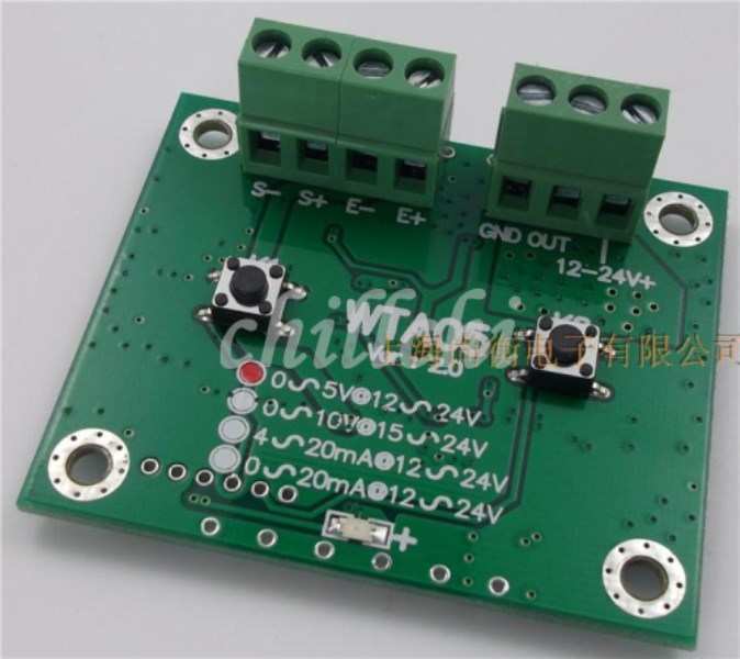
Wiring schematic diagram, such as the right:
12~24V+: External input power source;
OUT: Analog signal output;
GND: External input power cathode
E+: Sensor excitation voltage;
E-: Sensor excitation voltage negative;
S+ Sensor signal positive;
S-: Sensor signal negative;
Debug prompt:
- about0-5Vor0-10VApplication of voltage output, in order to avoid the influence of negative input power transmission line voltage drop of anode, input power (power) and the output voltage signal, using two wires, in one terminal, separated at the detection end user (see above), if a common line voltage the analog output signal accuracy decline leads to large error, or even can not be applied to;
- Calibration of load weight, analog output range, standard timed analog output setting calculation method:
Hypothesis: the maximum weight of the scale is100kgThe load used in the calibration is25kgWeights, analog output is4~20mAWhen the load is calibrated, the analog output=
Minimum analog value+(Maximum value of simulation-Minimum analog value*)Load weight.Maximum scale
= 4 +(20-4*)25.100
= 8 mA

