Brand Name:icchipcn.com
Condition:New
Type:Voltage Regulator
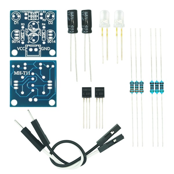
Function description: After the power is connected, the left and right two red LED (can be replaced by other color LED) flicker alternately, so anti
Multiple cycle, the higher the power supply voltage, the brighter the LED, changing the electrolytic capacitor capacity can change the speed of alternating flashing, the greater the capacity, flashing
The slower the blinking speed is, the smaller the capacity is and the faster the blinking speed is. The circuit is simple and easy to understand, the solder pad has been done with tin spraying process, welding is easier, welding
Point more beautiful! Especially suitable for friends and students who are beginning to learn electronics.
Circuit principle:
When the power supply is switched on, two triodes must compete for the pilot, but due to the differences in components, only a certain pipe pilot. If Q1 is on, then Q1 collector voltage drops, D1 is lit, and the left end of capacitor C1 is close to zero voltage. Since the voltage at both ends of capacitor cannot change suddenly, Q2 base is also pulled to nearly zero voltage, so that Q2 is cut off and D2 is not bright. As the power supply charges C1 through the resistor R2, the base voltage of the transistor Q2 gradually increases. When the voltage exceeds 0.6V, Q2 changes from the cut-off state to the conduction state, the collector voltage drops, and D2 is lit. At the same time, the decrease of collector voltage of transistor Q2 makes the base voltage of transistor Q1 jump down through the action of capacitor C2, Q1 changes from conduction to cut-off, and D1 goes out. In this way, two transistors in the circuit will take turns to conduct and stop, and two light-emitting diodes on the cycle of light. Changing the capacity of the capacitor can change the speed of the LED cycle.
Q1: What Is Your Product Warranty?
A: We Guarantee Our Product Is Fit For Its Normal User Purposes And Is Free From Defects In Materials Or Workmanship.
Q2: What Is Your Company Policy On Defective Goods?
A: Our Company Keep Items Quality For A Long Time. If There Are Any Defective Goods Due To
Production Defects Or Transportation Problem, Please Contact Us. Our Customer Service Team Will Provide Immediate Response To
Complaints. We Will Try Our Best To Give You A Good Resolve Way.
Q3: What Is Your MOQ (minimum Order Quantity)?
A: Generally Our Moq Is No Limited. Please Have More Discussion With Us If Your Combination Of Models Is Complicated.
Q4:how About Getting Samples From You?
A: We Will Send You The Samples After We Receive The Payment For Samples. The Buyer Shall Afford The Shipping Cost. Please Have A
Confirm With Us Which Shipping Way Do You Want.
Q5:about The Shipment: What Type Of Shipment Will You Use?
A: We Usually Ship The Products By Express(delivery It To Your Door) Or By Air Freight To Your Nearest Airport, Shipping Days:3-7
Working Days Depend On Destination;if The Order Quantity Is Large, We May Ship By Sea Container And The Best Ship Way Is By Sea,
Shipping Days: Over 20 Working Days Depend On Destination Port.
Q6:what Packing Do You Use?
A: Neutral Package With Airbag Or Customized Package.
Q7:how Much Are The Shipping Cost?
A:shipping Cost Is Charged By The Package's Weight And Related To The Shipping Methods You Choose And Your Destination.
Q8:how To Order?
Step1.Click (Add to Cart) Buy Directly On The Product Page, Or Add To Shopping Cart And Settle Together, Pay With Paypal,
Need your information, such as full name,country, city, detail address, post code, tax number ...
Step2. We Will Delivery by EMS POST, FedEx or DHL Within
3-5 Working Days After Payment Confirmed.
Setp3. Confirm Us Receipt of Products.

